- Technical Information
- 11 likes
- 109992 views
It is well known that in a single-phase motor, it is not enough to reverse the order of the power supply to the motor so that it changes direction of rotation, as in three-phase motors. If we perform this operation, the motors will always rotate in the same direction of rotation, this is because in single-phase power systems, in itself inside the motor, a rotating magnetic field is not generated, but pulsating, since adding another additional coil and feeding it with some offset from the other coil so that the pulsating magnetic field is translated into rotary. This is achieved by a coil in series with a capacitor.
If we reverse the two coils, the rotating magnetic field will be created in the same direction.
To change the direction of the magnetic field, and therefore the direction of rotation of the motor, we have to alternate the power on a single of the coils, it is indifferent which of the two is performed.
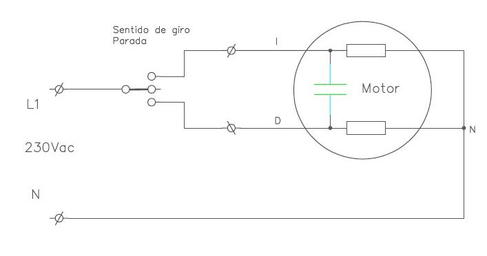
To make a turning inverter we can resort to 2 mounting schemes, commonly called 3 and 4 wires.
3-WIRE MOUNTING TURN INVERTER.
This assembly is often used in low power inverter systems when the control is done by switch, also widely used for the conversion of three-phase systems into single phases, since, in many cases, it allows the use of the same installed elements.
Depending on the engine manufacturer, we may need to fully identify all the elements that make up the engine to perform its connection. Poor connection can cause condenser breakage, so it is advisable to clearly identify the elements and take all necessary precautionary measures.
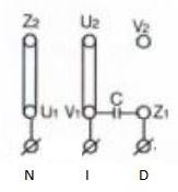
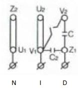
The connection of this type of inverter in the motors supplied by adajusa is done very easily.
Connectional motors half torque (1 capacitor)
Connection with high torque motors (2 capacitors)
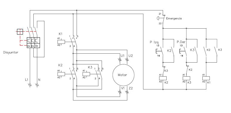
Commonly used in medium power machinery, when the inverter is made by contactors.
Engine connection is usually done very easily on the motor power terminal.
Attention: Do not forget to remove the plates from the motor connection terminals.
SWITCH TURN INVERTER.
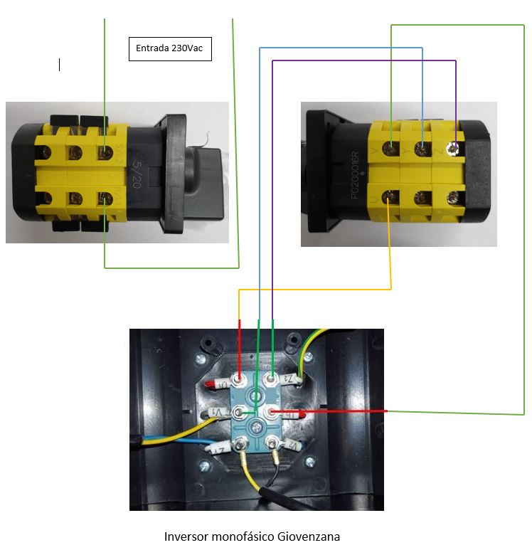
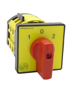
Inverter switches are also available, which allow the investment to be made at 4 wires, acting directly on an inverter with mechanical control. The type of inverter switch scheme to be used is the so-called 61270, in the following figure you can see the wiring that needs to be performed for the connection of said switch.
Please note that machine and engine guards are not included in the images.
Giovenzana brand inverter switch:
The power input will be connected between terminals L1 and L2.
The L1 coil will be connected between terminals U - V (switch) to U1-U2 (motor)
The L2 coil will be connected between terminals Y - Z (switch) to V1-Z2 (motor)
The pole reversal will be made by the inverter on the L2 coil, which is located between terminals V1 and Z2
ATTENTION: Do not forget to remove the plates from the motor connection terminals or install the protections for the line and motor.

